
Schematic diagram of an Arduino connected to a motor driver to control a DC motor. A simple PWM motor speed control circuit with diagram and schematic for low power dc motors.
Sensors Modules Dc Motor Sensors Modules

Types Of Dc Motors And Their Applications Electrical4u
Don T Ignore The Humble Brushed Dc Motor Mouser
The DC motor was the mainstay of electric traction drives on both electric and diesel-electric locomotives street-carstrams and diesel electric drilling rigs for many years.

Dc motor diagram. In this example you model a DC motor driven by a constant input signal that approximates a pulse-width modulated signal and look at the current and rotational motion at the motor output. There are controllers for brushed DC motors brushless DC motors as well as universal motors and they all allow operators to set desired motor behavior even though their mechanisms for doing so differ. The Pin diagram of the L293D Motor Driver IC along with the pin description is shown in the following image.
The armature is perpendicular to the axis of the cylinder. In this type of DC motor the armature and field windings are connected in series. Learn how to control DC motor using Arduino how to control DC motor speed and direction how to connect DC motor to Arduino how to program Arduino step-by-step.
Simply put a DC motor controller is any device that can manipulate the position speed or torque of a DC-powered motor. This is known as the Lorentz force. There are three input pins for each motor Input1 IN1 Input2 IN2 and Enable1 EN1 for Motor1 and Input3 Input4 and Enable2 for Motor2.
DC Motor Speed Control using PWM with PIC Microcontroller. For example if we want to automate our house doors ie if we want to open and close the doors automatically by detecting the person motor plays a vital role here. L298N Motor Driver Module details.
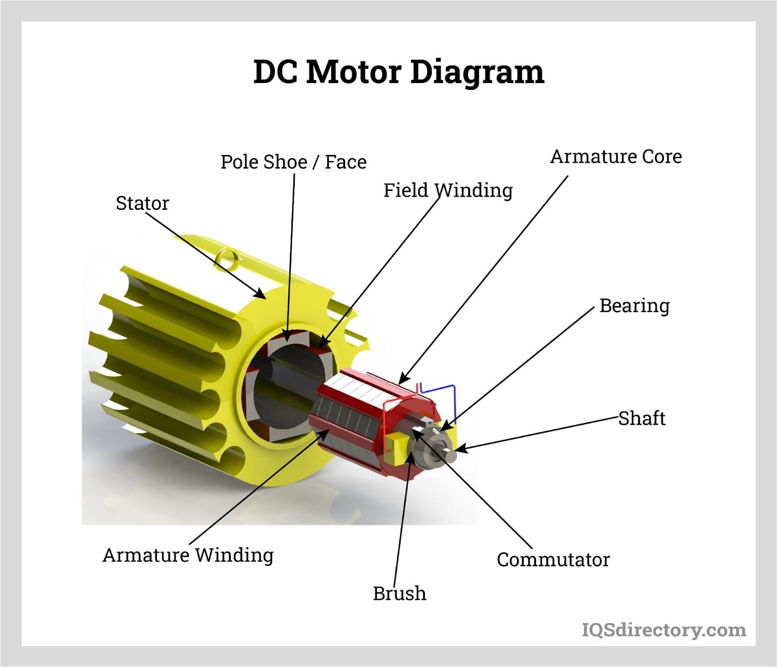
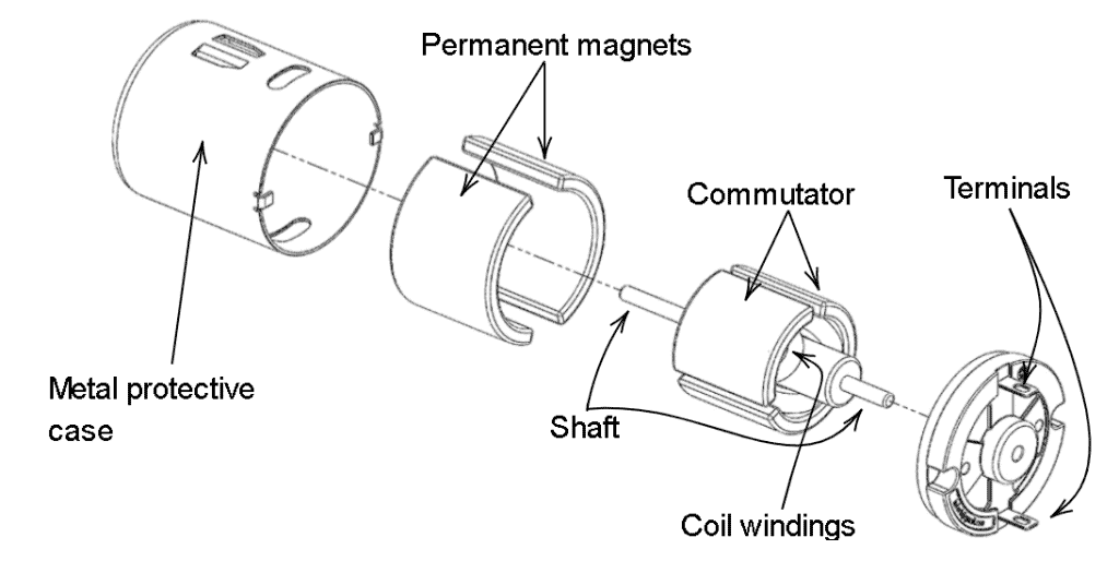
2 and its component layout in Fig. DC Motor Diagram Different Parts of a DC motor. A brushed DC electric motor is an internally commutated electric motor designed to be run from a direct current power source.
Following is the schematic diagram of the DC motor interface to Arduino Uno board. Select Blocks to Represent System Components. This wiring diagram shows how to configure a DPDT switch as an H Bridge configuration for reversible blind and shade tubular DC motors.
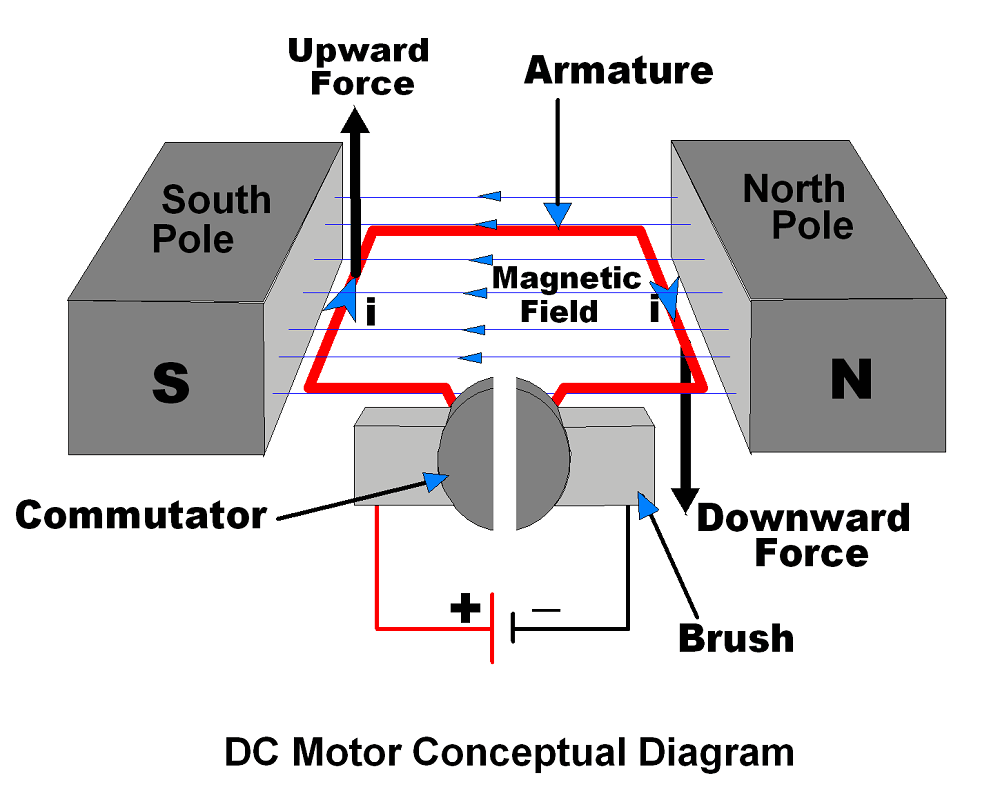
The resistance of the series field winding Rs is much smaller than the armature resistance Ra The flux produced is proportional to the field current but in this 𝐼𝑓 𝐼 𝑎 thus 𝐼𝑎 Thus flux can never become constant in dc series motor as load changes If and. DC motor is the essential part of the different projects and our daily life. The DC motor working principle is that a current-carrying conductor experiences a mechanical force when placed in a magnetic field.
To see the completed model open the PWM-Controlled DC Motor example. The Arduino and switch are connected as described in the drawing above. Brushed motors were the first commercially important application of electric power to driving mechanical energy and DC distribution systems were used for more than 100 years to operate motors in commercial and industrial buildings.
Turning VR1 counter-clockwise lowers the duty cycle which in turn lowers the speed of the motor and vice versa. PWMA is connected to the Arduinos digital. Reversing polarity of DC shade motors can be accomplished with a simple DPDT double pole double throw switch.
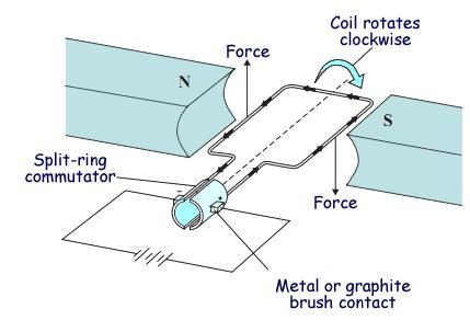
DC motor working principle is similar to the working principle of a DC generator. The speed of the BLDC motor can be controlled by varying the duty cycle of the PWM signal. Here in this Arduino Motor Speed Control project the speed can be controlled by rotating the knob of potentiometer.
A single-side PCB for the brushless DC motor driver is shown in Fig. This easy to make pwm dc motor controller is made using IC CD40106B. Both the field coils provide for the required amount of magnetic flux that links with the armature coil and brings about the torque necessary to.
When voltage is applied current flows from power supply terminals through the series winding and armature winding. An electric motor is an electrical machine which converts electrical energy into mechanical energy. DC Motors are further classified in to.
In a series motor electric power is supplied between one end of the series field windings and one end of the armature. A motor driver has been added and is connected as follows. DC motors are one of the commonly used motors in different applications like electronic toys power tools portable fans etc.
The L298N motor driver is based on the H-bridge configuration an H-bridge is a simple circuit that lets us control a DC motor to go backward or forward which is useful in controlling the direction of rotation of a DC motor. The detailed instruction code wiring diagram video tutorial line-by-line code explanation are provided to. The introduction of DC motors and an electrical grid system to run machinery starting in the 1870s started a new second Industrial Revolution.
A DC supply is converted to rotation or movement. Follow the next schematic diagram to wire the DC motor and the L298N motor driver to the ESP32. Similarly in robotics vacuum blowers and air conditioners DC motor has a wide range of applications.
The DC shunt motor circuit diagram is shown below and the flow of current and voltage being supplied to the motor from the supply can be given by Itotal E. The DC motor requires a big jump in current to move so the motors should be powered using an external power source from the ESP32. Two push button switches are connected to 1st and 2nd pins of PORTD which is used to control the duty ratio of the generated PWM.
Whenever a current carrying conductor is placed in a magnetic field it. DC MOTOR WORKING PRINCIPLE. Therefore construction of a DC motor is same as that of a DC generator.
DC Series Motor. Ive used L293D Motor Driver IC for controlling a DC Motor with Raspberry Pi. L298N motor driver Module.
Theoretically the same DC machine can be used as a motor or generator. As an example were using 4AA batteries. It is a very common motor driver IC which is capable of driving two motors with individual currents up to 600mA.
A series wound DC motor like in the case of shunt wound DC motor or compound wound DC motor falls under the category of self-excited DC motors and it gets its name from the fact that the field winding in this case is connected internally in series to the armature windingThus the field winding are exposed to the entire armature current unlike in the case of a shunt motor. VDD should be connected to 5V and VSS to GND. The above diagram shows how to connect the L298 IC to control two motors.
DC Shunt Motor Circuit Diagram In case of the shunt wound DC motor this current supply will divide into two ways like Ia Ish where Ia will supply throughout the Ra resistance armature winding. A compound wound DC motor also known as a DC compound motor is a type of self-excited motor and is made up of both series the field coils S 1 S 2 and shunt field coils F 1 F 2 connected to the armature winding as shown in the figure below. DC motor is the most used motor in Robotics and electronics projectsFor controlling the speed of DC motor we have various methods like the speed can be automatically controlled based on temperature but in this project PWM method will be used to control the speed of DC motor.
Working principle of a DC motor. The basic working principle of a DC motor is. VDD and VSS of the pic microcontroller is not shown in the circuit diagram.
A DC Motor is a type of electric motor that converts DC electrical power to mechanical power ie. And the direction of this force is given by FLEMINGS LEFT-HAND RULE. A DC motor is composed of the following main parts.
DC Series Motor Circuit Diagram. The armature of a DC motor is a cylinder of magnetic laminations that are insulated from one another.
Dc Motors How Do They Work Construction Working Principle Of A Dc Motor Electrical4u Youtube
How To Build A Dc Motor Circuit


Dc Motor Diagram And Constructional Parts Etechnog
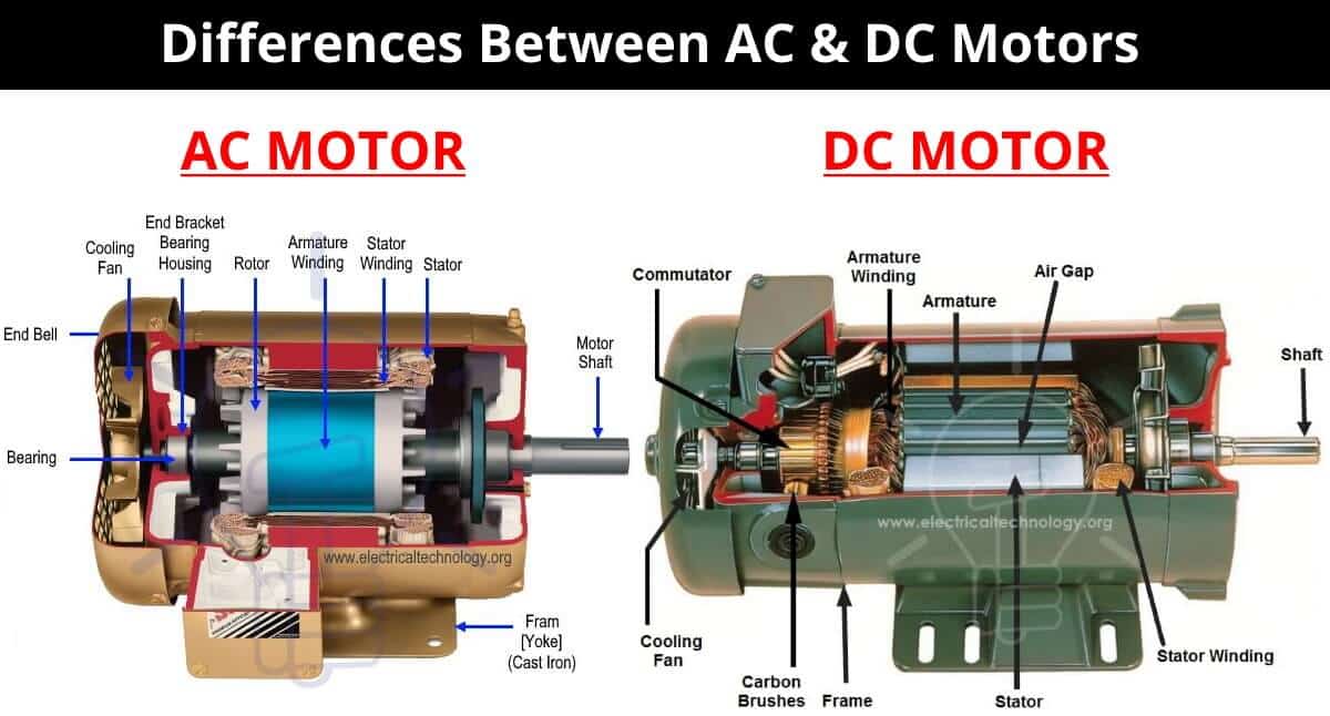
What Is The Main Difference Between Ac And Dc Motor
Dc Motor What Is It How Does It Work Types Uses
Introduction To Using Dc Motors On The Raspberry Pi Circuit Basics
1

Dc Motor Connections Inst Tools


